Lighting & Texturing
04/04/2008
Lights
If you take a look around yourself, you’ll see lights exist anywhere. Even in darkest places you may think off a little bit light exist. It doesn’t matter it is day or night, indoor or outdoor, lights exist anywhere.
Introduction to lights
When we talk about light, several behaviors of light come into our mind. In this article my aim is not to cover any of them (although we will use diffusion and reflection); I just want to give readers brief introduction about each one. The following list presents some categories into which we can place light in terms of its behavior (See Figures 1-10):
- Reflection. Reflection is the throwing or bouncing back of light as it hits a surface.
- Refraction. Refraction is the bending or turning of light as it crosses from one medium to another; for example, in passing from air to glass or water, the light gets bent.
- Transmission. Transmission of light is the conduction or conveying of light through a medium.
- Diffraction. Diffraction is the apparent bending of light around an edge that results in intensity and directional changes. Diffraction produces light bands.
- Interference. Interference is the wavelike interaction of light that results in amplification, cancellation, or composite generation of the resultant light wave.
- Scattering. Scattering is the spreading or dispersal of light as it interacts with matter or media. It is the multiple reflection of light in different directions.
- Diffusion. Diffusion is the even scattering of light by reflection from a surface. Diffusion also refers to the transmission of light through a translucent material.
- Absorption. Absorption is the non-conductance or retention of light by a matter or media that does not result in either reflection or transmission.
- Polarization. Polarization is the selective transmission of light based on its orientation. When light is reflected or refracted, its orientation and alignment change.
- Dispersion. Dispersion is the effect of light being separated or broken into different wavelengths because the light passed through a second medium that has a different refraction index from the first. This is the common prism effect or grating effect. To work, dispersion requires the presence of two different media. It is the change in the index of refraction as a function of the wavelength in a transparent medium.
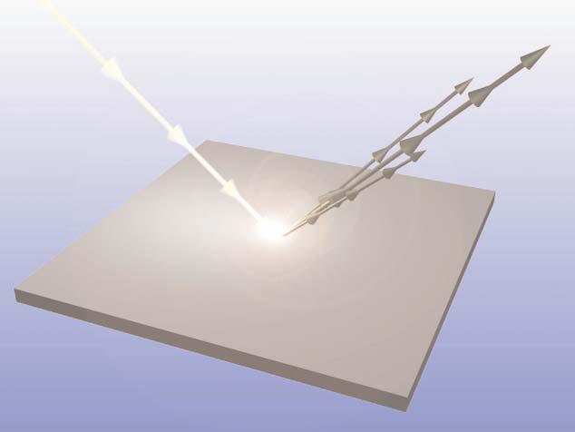
Figure 1 - Reflection
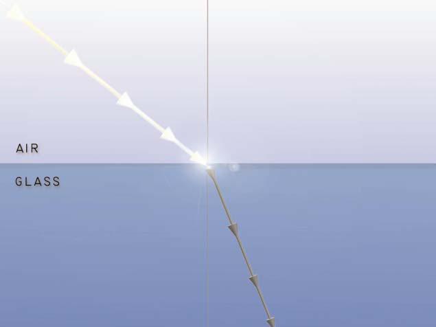
Figure 2 - Refraction
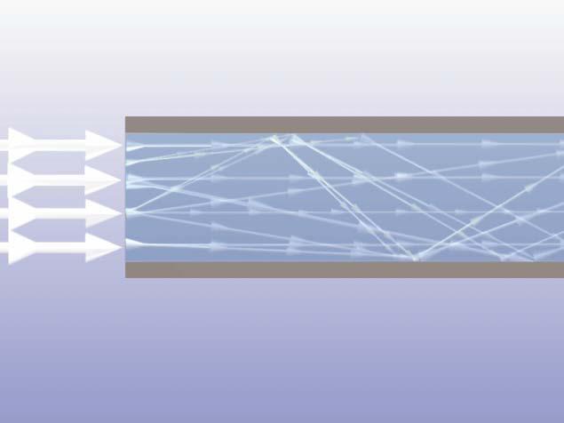
Figure 3 - Transmission
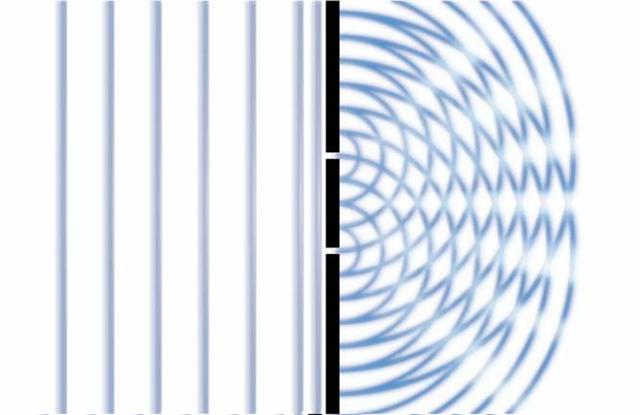
Figure 4 - Diffraction
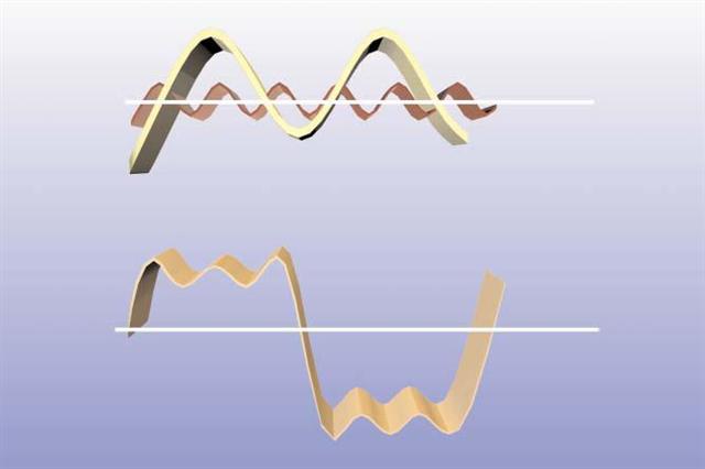
Figure 5 - Interferences
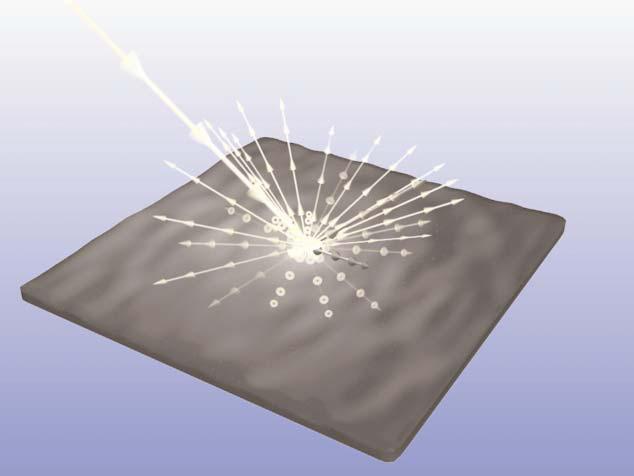
Figure 6 - Scattering
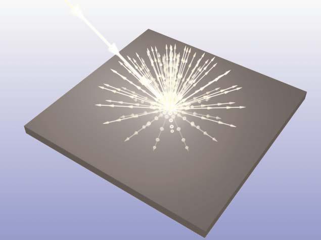
Figure 7 - Diffusion
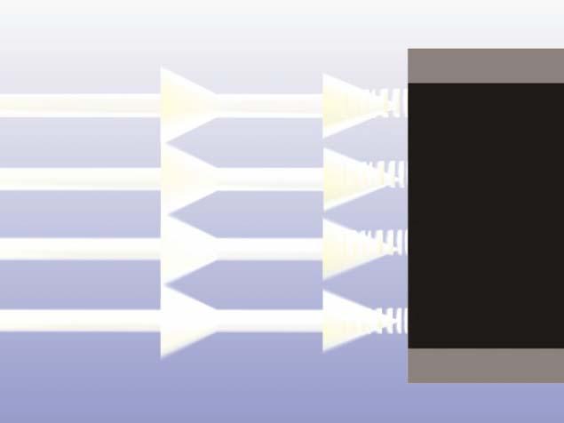
Figure 8 - Absorption
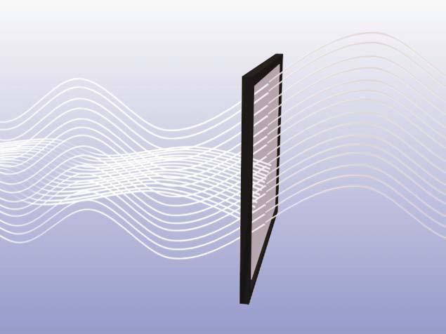
Figure 9 - Polarization
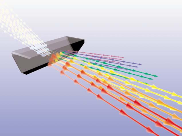
Figure 10 - Dispersion
Note:
Figures 1- 10 are taken from book 3D Lighting: History, Concepts, and Techniques. Jenifer L. Niles
The law of reflection
The law of reflection states that the angle of the reflection equals the angle of the incidence as relative to the surface’s normal. This means that the reflected light’s angle would be the same as the incoming light’s angle. A Surface normal is a line perpendicular to the reflecting surface at the point of incidence. Figure 11 illustrates reflection law:
Figure 11 - Law of Reflection
Figure 11 - Law of Reflection
Light sources
In real world and in 3D computer graphics usually we have 4 different types of light. Although in 3D computer graphics we may have more than these 4 types, I’ll describe only these types of light in this article:
- Ambient Light
- Directional Light
- Point Light
- Spot Light
Ambient lights
Ambient is a light that exits everywhere. This light arises from reflection of light in nearby environment. Ambient light seems to come from many directions, intensity of lights are all equal.
So using ambient light provides an approximation of general brightness. For example suppose at night when the lights are off you wake up and go to kitchen to drink a glass of water. Amount of light in the room is enough to find your way to kitchen but you cannot see details of rooms. Let’s say this type of light is called Ambient. We add ambient light to our final surface color; below code shows this fact:
So using ambient light provides an approximation of general brightness. For example suppose at night when the lights are off you wake up and go to kitchen to drink a glass of water. Amount of light in the room is enough to find your way to kitchen but you cannot see details of rooms. Let’s say this type of light is called Ambient. We add ambient light to our final surface color; below code shows this fact:
return FinalColor + AmbientColor; |
Since ambient light a low-intensity one, we often set small values for this light in our equations (Like float4 (0.15, 0.15, 0.15, 1)).
Directional lights
Directional (infinite) light is a type of light that come from far away. Lights rays in this light model are parallel to each other. Directional lights are useful when we want to place a sun in our game. Intensity of this light does not diminish over distance. Figure 12 is an illustration of a directional light:
Figure 12 - Directional light
Figure 12 - Directional light
Point lights
Point lights radiate light equally to any direction. Their major usage is for indoor games to place light bulbs into the room. Intensity of point lights decrease over distance. Figure 13 shows a point light radiating light to all direction from a single point:
Figure 13 - Point light
Below code determines how much light our surface will receive from light source for point light:
Figure 13 - Point light
Below code determines how much light our surface will receive from light source for point light:
float3 PositionInWorld = mul(float4(Position, 1.0f), World).xyz; float3 LightDirection = mul((LightPosition - PositionInWorld) / LightRange); float Attenuation = saturate(1.0f - dot(LightDirection, LightDirection)); |
Spot lights
Spot light are similar to point light; but in the case of spot light we have a preferred light direction.
Intensity of spot light like point lights decrease over distance and also by another factor called spot light effect. Each spot light has to angles: inner cone angle and outer cone angle. Figure 14 illustrates these angles:
Figure 14 - Spot light and cone angles
This HLSL code shows how to calculate spot light effect:
float GetSpotLightEffect(float3 lightDirection, float3 spotDirection)
{
    float2 CosineVector = cos(float2(LightSpotOuterCone, LightSpotInnerCone) * 0.5f);
    float LightDotSpot = dot(-lightDirection, normalize(spotDirection));
    return smoothstep(CosineVector.x, CosineVector.y, LightDotSpot);
} |
In above code I put inner and outer cone angles into a float2 to speed up calculation. The aim is to get cosine of inner and outer angles. Having spot light effect, we multiply attenuation factor by the spot light effect:
float Attenuation = saturate(1.0f - dot(LightDirection, LightDirection)); Attenuation *= GetSpotLightEffect(NormalizedLightDirection, LightDirection); |
Materials
Materials are simply a definition of how an object assigned that material will reflect incident light.
As you might expect, this implies a dependency on the characteristics of the incident light.
Here we define some variables needed for our next steps:
As you might expect, this implies a dependency on the characteristics of the incident light.
Here we define some variables needed for our next steps:
#define LIGHT_DIRECTIONAL 0
#define LIGHT_POINT 1
#define LIGHT_SPOT 2
int LightType = 0;
float3 LightDirection = float3(0, -1, -1);
float3 LightPosition = float3(0, 15, 0);
float LightSpotInnerCone = 0.3490;
float LightSpotOuterCone = 0.6981;
float LightRange = 30;
float4 MaterialAmbient = float4(0.2, 0.2, 0.2, 1.0);
float4 MaterialDiffuse = float4(0.8f, 0.8f, 0.8f, 1.0f);
float4 MaterialSpecular = 0;
float MaterialShininess = 0;
float4x4 World;
float4x4 WorldIT;
float4x4 WorldViewProjection;
float3 CameraPosition;
texture2D DiffuseTexture;
texture2D NormalTexture;
sampler2D DiffuseSampler = sampler_state
{
Texture = |
Lighting equation: diffuse, specular
Before I jump and talk about diffuse and specular color let’s define some useful vectors. Light vector is like a ray rising from surface at sampling point to light source. View direction goes from surface to viewer’s eye. Normal vector is perpendicular to the surface and half vector is a vector between light direction and view direction. We calculate half vector by using this equation:
float3 HalfVector = normalize(LightDirection + ViewDirection); |
In above equation LightDirection and ViewDirection must be unit length. We normalize sum of them to make sure half vector is unit length as well.
Figure 15 illustrates these vectors:
Figure 15
Diffuse is main color of our surface. When we say ‘that car is blue’ we are talking about diffuse color of that car. We can set a constant value for diffuse color or get the color from the mapped texture (or both, in this case we multiply constant value by obtained color from texture). Then we need to calculate dot product between light direction and view direction. This value will be multiplied by our diffuse color and produce final color of surface. Closer angles between light vector and surface normal causes brighter surface:
float NormalDotLight = saturate(dot(Normal, LightDirection)); float3 Diffuse = DiffuseColor * NormalDotLight; |
Specular color is a small shininess on the surface when the light reflects in a direction same or near the view direction. In fact it is a result of the light from the source reflecting directly off the surface of the object to your eye. Figure 16 illustrates diffuse and specular colors:
Figure 16 - Diffuse and Specular colors
The color of this highlight is adjustable because in the real world, the color of a specular highlight is not just a function of the color of the incident light and the diffuse and ambient colors of the object. The reflected light might take on different colors because not all components are reflected equally. Altering the color of the highlight can allow more flexibility in achieving realistic results at a low cost. MaterialSpecular enables us define color of specular highlight. Finally, the “power” of the specular highlight can be controlled; the short version of this parameter is that you can control the size of the “bright spot” on the object’s surface, to alter the perceived shininess of the object: higher power provides a smaller highlight.
Here is required code to calculate specular highlight:
float NormalDotHalf = saturate(dot(Normal, HalfVector)); float FinalSpecular = MaterialSpecular * NormalDotHalf; |
To calculate power of specular we need to test if diffuse color is not black. If surface has a close angle to the light direction, surface will look black; in this case we do not have specular and amount of specular power is equal to zero:
float NormalDotLight = saturate(dot(Normal, LightDirection));
float SpecularPower = (NormalDotLight == 0.0f) ?
                        0.0f :
pow(NormalDotHalf, MaterialShininess); |
Here is HLSL code to get the final color by calculating diffuse and specular colors:
// LightDirection and ViewDirection must be normalized.
float4 GetFinalColor(float3 Normal,
                     float3 LightDirection,
                     float3 ViewDirection)
{
    float3 HalfVector = normalize(LightDirection + ViewDirection);

    float NormalDotLight = saturate(dot(Normal, LightDirection));
    float NormalDotHalf = saturate(dot(Normal, HalfVector));
    float SpecularPower = (NormalDotLight == 0.0f) ?
                            0.0f :
                            pow(NormalDotHalf, MaterialShininess);

    return MaterialAmbient +
            (MaterialDiffuse * NormalDotLight) +
            (MaterialSpecular * SpecularPower);
} |
Texturing techniques
In this article I’ll describe several texture mapping techniques:
Figure 17 - Relief Mapping
Figure 18 - Parallax Mapping
Figure 19 - Normal Mapping
Figure 20 - Diffuse Mapping
- Diffuse Mapping
- Normal Mapping
- Parallax Mapping
- Relief Mapping
Figure 17 - Relief Mapping
Figure 18 - Parallax Mapping
Figure 19 - Normal Mapping
Figure 20 - Diffuse Mapping
Diffuse Mapping
Diffuse Mapping is simplest texturing technique. Using lighting equation we can calculate diffuse factor and specular shininess and ambient color. In final step we get a pixel from diffuse map and multiply it by result of lighting equation.
Here is HLSL code of vertex shader:
Here is HLSL code of vertex shader:
VS_OUTPUT DiffuseMapping_VertexShader(float3 Position : POSITION,
                                      float2 TextureCoordinate : TEXCOORD0,
                                      float3 Normal : NORMAL)
{
    VS_OUTPUT OUT;

    float3 PositionInWorld = mul(float4(Position, 1.0f), World).xyz;
    OUT.Position = mul(float4(Position, 1.0f), WorldViewProjection);
    OUT.Normal = Normal;
    OUT.TextureCoordinate = TextureCoordinate;
    OUT.ViewDirection = normalize(CameraPosition - PositionInWorld);
    OUT.LightDirection = -LightDirection;
    OUT.Diffuse = MaterialDiffuse * LightDiffuse;
    OUT.Specular = MaterialSpecular * LightSpecular;

    if(LightType == LIGHT_DIRECTIONAL)
    {
        OUT.LightDirection = -LightDirection;
    }
    else if(LightType == LIGHT_POINT)
    {
        OUT.LightDirection = (LightPosition - PositionInWorld) / LightRange;
    }
    else if(LightType == LIGHT_SPOT)
    {
        OUT.LightDirection = (LightPosition - PositionInWorld) / LightRange;
    }
    return OUT;
} |
We multiply final diffuse color from lighting equation by the texture color in pixel shader:
float4 DiffuseMapping_PixelShader(VS_OUTPUT IN) : COLOR
{
    float3 NormalizedLightDirection = normalize(IN.LightDirection);

    float4 FinalColor = GetFinalColor(IN.Normal,
                                      NormalizedLightDirection,
                                      IN.ViewDirection,
                                      IN.Diffuse,
                                      IN.Specular);

    FinalColor *= tex2D(DiffuseSampler,
                        IN.TextureCoordinate);

    if(LightType == LIGHT_POINT)
    {
        float Attenuation = saturate(1.0f - dot(IN.LightDirection,
                                                IN.LightDirection));
        FinalColor *= Attenuation;
    }
    else if(LightType == LIGHT_SPOT)
    {
        float Attenuation = saturate(1.0f - dot(IN.LightDirection,
                                                IN.LightDirection));

        FinalColor *= Attenuation *
                        GetSpotLightEffect(NormalizedLightDirection,
                                           LightDirection);
    }
    return FinalColor;
} |
Normal Mapping
Normal Mapping like Diffuse Mapping uses basic light equation. The only difference between these two effects is how we obtain surface normal. Instead of using vertex’s normal for whole surface (all of pixels), in normal mapping technique we have a texture additional to the diffuse map called NormalTexture that describes normal for every pixel (As I mentioned in previous section, in diffuse mapping technique we have a normal vector for each vertex). Using this per-pixel technique, our flat object will look with much more details. This is because different normal vectors result in different amount of absorbing light and our final color will look better.
Before we start with HLSL code, let’s refresh our knowledge about coordinate-spaces. In 3D systems we can define many spaces. For example in World Space coordinates (also known as Human Body Space), we define X axis to our right hand direction, Y axis is on top of our head and points to sky and Z axis is behind us. This means when we look forward we are looking in –Z direction.
Now let’s define a new coordinate system: Tangent Space coordinates. In Tangent Space like any other coordinate space we have 3 axes: Tangent (X), BiNormal (Y) and Normal (Z). To convert positions from world space to tangent space we need to multiply vertices by TBN matrix composed from Tangent, BiNormal and Normal unit vectors:
Figure 21 illustrates tangent space axes:
Figure 21 - Tangent space coordinates
Where P’ is new vertex position in tangent space, P is vertex position in world space, T is Tangent unit axis, B is BiNormal unit axis and N is Normal unit axis.
Here is a code to define a custom vertex that has ability to hold Tangent and BiNormal vectors additional to Normal vector in C#:
public struct VertexPositionTangentBinormalNormalTexture
{
    public Vector3 Position;
    public Vector3 Tangent;
    public Vector3 Binormal;

    public Vector3 Normal;
    public Vector2 TextureCoordinate;
    public static VertexElement[] VertexElements
    {
        get
        {
            return new VertexElement[]
            {
                new VertexElement(0,
                                  0,
                                  VertexElementFormat.Vector3,
                                  VertexElementMethod.Default,
                                  VertexElementUsage.Position,
                                  0),

                new VertexElement(0,
                                  12,
                                  VertexElementFormat.Vector3,
                                  VertexElementMethod.Default,
                                  VertexElementUsage.Tangent,
                                  0),

                new VertexElement(0,
                                  24,
                                  VertexElementFormat.Vector3,
                                  VertexElementMethod.Default,
                                  VertexElementUsage.Binormal,
                                  0),

                new VertexElement(0,
                                  36,
                                  VertexElementFormat.Vector3,
                                  VertexElementMethod.Default,
                                  VertexElementUsage.Normal,
                                  0),

                new VertexElement(0,
                                  48,
                                  VertexElementFormat.Vector2,
                                  VertexElementMethod.Default,
                                  VertexElementUsage.TextureCoordinate,
                                  0)
            };
        }
    }
    public static int SizeInBytes
    {
        get
        {
            return 12 + 12 + 12 + 12 + 8;
        }
    }
} |
Having P’ as position in tangent space we should transform any other lighting parameters such as light direction, view direction and etc to tangent space to transformation occur in same coordinate systems. Remaining calculations are same as diffuse mapping and they’re straight forward. Here is required HLSL code to define TBN matrix and transform anything to tangent space, we can get BiNormal directly from input or calculate it by cross product of normal and tangent vectors:
VS_OUTPUT NormalMapping_VertexShader(float3 Position : POSITION,
                                     float2 TextureCoordinate : TEXCOORD0,
                                     float3 Normal : NORMAL,
                                     float4 Tangent : TANGENT)
{
    VS_OUTPUT OUT;

    float3 n = mul(Normal, (float3x3)WorldIT);
    float3 t = mul(Tangent.xyz, (float3x3)WorldIT);
    float3 b = cross(n, t) * Tangent.w;
    float3x3 TangentBinormalNormal = float3x3(t.x, b.x, n.x,
                                              t.y, b.y, n.y,
                                              t.z, b.z, n.z);

    float3 PositionInWorld = mul(float4(Position, 1.0f), World).xyz;
    OUT.Position = mul(float4(Position, 1.0f), WorldViewProjection);
    OUT.TextureCoordinate = TextureCoordinate;
    OUT.ViewDirection = normalize(
                            mul(CameraPosition - PositionInWorld,
                                TangentBinormalNormal));

    OUT.Diffuse = MaterialDiffuse * LightDiffuse;
    OUT.Specular = MaterialSpecular * LightSpecular;

    if(LightType == LIGHT_DIRECTIONAL)
    {
        OUT.SpotDirection = 0;
        OUT.LightDirection = mul(-LightDirection, TangentBinormalNormal);
    }
    else if(LightType == LIGHT_POINT)
    {
        OUT.SpotDirection = 0;
        OUT.LightDirection = mul((LightPosition - PositionInWorld) / LightRange,
                                 TangentBinormalNormal);
    }
    else if(LightType == LIGHT_SPOT)
    {
        OUT.LightDirection = mul((LightPosition - PositionInWorld) / LightRange,
                                 TangentBinormalNormal);

        OUT.SpotDirection = mul(LightDirection,
                                TangentBinormalNormal);
    }
    return OUT;
}

float4 NormalMapping_PixelShader(VS_OUTPUT IN) : COLOR0
{
    float3 NormalizedLightDirection = normalize(IN.LightDirection);

    float3 Normal = normalize(tex2D(NormalMap,
                                    IN.TextureCoordinate).rgb * 2.0f - 1.0f);

    float4 FinalColor = GetFinalColor(Normal,
                                      NormalizedLightDirection,
                                      IN.ViewDirection,
                                      IN.Diffuse,
                                      IN.Specular);

    FinalColor *= tex2D(DiffuseSampler, IN.TextureCoordinate);

    if(LightType == LIGHT_POINT)
    {
        float Attenuation = saturate(1.0f - dot(IN.LightDirection,
                                                IN.LightDirection));
        FinalColor *= Attenuation;
    }

    else if(LightType == LIGHT_SPOT)
    {
        float Attenuation = saturate(1.0f - dot(IN.LightDirection,
                                                IN.LightDirection));

        FinalColor *= Attenuation * GetSpotLightEffect(NormalizedLightDirection,
                                                       IN.SpotDirection);
    }
    return FinalColor;
} |
Parallax Mapping
Parallax mapping is per-pixel ray tracing of a height field in tangent space. With parallax mapping objects will have more apparent depth and thus greater realism with less of an Effect on the performance comparing with normal mapping. In parallax mapping technique we have an extra texture called Height texture. We read height information from this texture and move our diffuse map and normal map sampling position by an offset called parallax offset. We calculate parallax offset by using this HLSL code:
float2 GetParallaxCorrectSamplingPosition(float2 texCoords, float3 halfVector)
{
    float offset = (tex2D(HeightMap, texCoords).r) * HeightScale + HeightBias;
    return texCoords + (offset * halfVector.xy);
} |
Where HeightScale and HeightBias as their names imply are scale and bias of depth.
Figure 22 illustrates parallax mapping algorithm:
Figure 22 - Parallax mapping algorithm
Now we will change our normal mapping shader from previous section to use new texture coordinates, vertex shader is same as normal mapping vertex shader:
Figure 22 illustrates parallax mapping algorithm:
Figure 22 - Parallax mapping algorithm
Now we will change our normal mapping shader from previous section to use new texture coordinates, vertex shader is same as normal mapping vertex shader:
VS_OUTPUT ParallaxMapping_VertexShader(float3 Position : POSITION,
                                       float2 TextureCoordinate : TEXCOORD0,
                                       float3 Normal : NORMAL,
                                       float4 Tangent : TANGENT)
{
    VS_OUTPUT OUT;

    float3 n = mul(Normal, (float3x3)WorldIT);
    float3 t = mul(Tangent.xyz, (float3x3)WorldIT);
    float3 b = cross(n, t) * Tangent.w;

    float3x3 TangentBinormalNormal = float3x3(t.x, b.x, n.x,
                                              t.y, b.y, n.y,
                                              t.z, b.z, n.z);

    float3 PositionInWorld = mul(float4(Position, 1.0f), World).xyz;
    OUT.Position = mul(float4(Position, 1.0f), WorldViewProjection);
    OUT.TextureCoordinate = TextureCoordinate;
    OUT.ViewDirection = normalize(mul(CameraPosition - PositionInWorld,
                                      TangentBinormalNormal));

    OUT.Diffuse = MaterialDiffuse * LightDiffuse;
    OUT.Specular = MaterialSpecular * LightSpecular;

    if(LightType == LIGHT_DIRECTIONAL)
    {
        OUT.SpotDirection = 0;
        OUT.LightDirection = mul(-LightDirection, TangentBinormalNormal);
    }
    else if(LightType == LIGHT_POINT)
    {
        OUT.SpotDirection = 0;
        OUT.LightDirection = mul((LightPosition - PositionInWorld) / LightRange,
                                 TangentBinormalNormal);
    }
    else if(LightType == LIGHT_SPOT)
    {
        OUT.LightDirection = mul((LightPosition - PositionInWorld) / LightRange,
                                 TangentBinormalNormal);

        OUT.SpotDirection = mul(LightDirection,
                                TangentBinormalNormal);
    }
    return OUT;
} |
And pixel shader has a small change:
float4 ParallaxMapping_PixelShader(VS_OUTPUT IN) : COLOR0
{
    float3 HalfVector = normalize(IN.LightDirection + IN.ViewDirection);
    float2 TextureCoordinate =
                GetParallaxCorrectSamplingPosition (IN.TextureCoordinate,
                                                    HalfVector);

    float3 Normal = normalize(tex2D(NormalMap,
                                    TextureCoordinate).rgb * 2.0f - 1.0f);
    float3 NormalizedLightDirection = normalize(IN.LightDirection);

    float NormalDotLight = saturate(dot(Normal, LightDirection));
    float NormalDotHalf = saturate(dot(Normal, HalfVector));

    float SpecularPower = (NormalDotLight == 0.0f) ?
                            0.0f :
                            pow(NormalDotHalf, MaterialShininess);

    float4 FinalColor = (MaterialAmbient * LightAmbient) +
                        (IN.Diffuse * NormalDotLight) +
                        (IN.Specular * SpecularPower);

    FinalColor *= tex2D(DiffuseSampler, TextureCoordinate);

    if(LightType == LIGHT_POINT)
    {
        float Attenuation = saturate(1.0f - dot(IN.LightDirection,
                                                IN.LightDirection));
        FinalColor *= Attenuation;
    }
    else if(LightType == LIGHT_SPOT)
    {
        float Attenuation = saturate(1.0f - dot(IN.LightDirection,
                                                IN.LightDirection));

        FinalColor *= Attenuation * GetSpotLightEffect(NormalizedLightDirection,
                                                       IN.SpotDirection);
    }

    return FinalColor;
} |
Relief Mapping
Relief mapping like parallax mapping simulates depth on the surface. But unlike parallax mapping we do not need to read height values from HeightTexture. Relief mapping technique extracts height values from normal texture which is called ReliefTexture here. Using this height value like parallax mapping we calculate an offset for texture sampling position. Below code shows how to extract surface normal and new texture sampling position from ReliefTexture:
float3 GetNormalFromReliefTexture(float2 TextureCoordinate)
{
    float3 Normal = tex2D(ReliefSampler, TextureCoordinate).rgb;
    Normal.xy = 2 * Normal.xy - 1;
    Normal.y = -Normal.y;
    Normal.z = sqrt(1.0 - Normal.x * Normal.x - Normal.y * Normal.y);

    return Normal;
}
float2 GetReliefCorrectSamplingPosition(float2 texCoord, float3 viewDirection)
{
    float3 TextureCoordinate = float3(texCoord, 0);
    float3 v = viewDirection;

    v.z = abs(v.z);
    float DepthBias = 1.0 - v.z;
    DepthBias *= DepthBias;
    DepthBias *= DepthBias;
    DepthBias = 1.0 - DepthBias * DepthBias;
    v.xy *= DepthBias;

    v.xy *= HeightScale;

    const int LinearSteps = 15;
    const int BinarySteps = 6;

    v /=  v.z * LinearSteps;

    int i;
    for(i = 0; i *lt; LinearSteps; i++)
    {
        float4 tex = tex2D(ReliefSampler, TextureCoordinate.xy);

        if (TextureCoordinate.z < tex.w)
        {
            TextureCoordinate += v;
        }
    }

    for(i = 0; i < BinarySteps; i++)
    {
        v *= 0.5;
        float4 tex = tex2D(ReliefSampler, TextureCoordinate.xy);

        if (TextureCoordinate.z < tex.w)
        {
            TextureCoordinate += v;
        }
        else
        {
            TextureCoordinate -= v;
        }
    }
    return TextureCoordinate;
} |
Vertex shader for relief mapping is same as parallax mapping’s vertex shader:
VS_OUTPUT ReliefMapping_VertexShader(float3 Position : POSITION,
                                     float2 TextureCoordinate : TEXCOORD0,
                                     float3 Normal : NORMAL,
                                     float4 Tangent : TANGENT)
{
    VS_OUTPUT OUT;

    float3 n = mul(Normal, (float3x3)WorldIT);
    float3 t = mul(Tangent.xyz, (float3x3)WorldIT);
    float3 b = cross(n, t) * Tangent.w;
    float3x3 TangentBinormalNormal = float3x3(t.x, b.x, n.x,
                                              t.y, b.y, n.y,
                                              t.z, b.z, n.z);
    float3 PositionInWorld = mul(float4(Position, 1.0f), World).xyz;

    OUT.Position = mul(float4(Position, 1.0f), WorldViewProjection);
    OUT.ViewDirection = normalize(mul(CameraPosition - PositionInWorld,
                                      TangentBinormalNormal));
    OUT.TextureCoordinate = TextureCoordinate;
    OUT.Diffuse = MaterialDiffuse * LightDiffuse;
    OUT.Specular = MaterialSpecular * LightSpecular;

    if(LightType == LIGHT_DIRECTIONAL)
    {
        OUT.SpotDirection = 0;
        OUT.LightDirection = mul(-LightDirection, TangentBinormalNormal);
    }
    else if(LightType == LIGHT_POINT)
    {
        OUT.SpotDirection = 0;
        OUT.LightDirection = mul((LightPosition - PositionInWorld) / LightRange,
                                 TangentBinormalNormal);
    }
    else if(LightType == LIGHT_SPOT)
    {
        OUT.LightDirection = mul((LightPosition - PositionInWorld) / LightRange,
                                 TangentBinormalNormal);

        OUT.SpotDirection = mul(LightDirection,
                                TangentBinormalNormal);
    }
    return OUT;
} |
Pixel shader needs a small change from parallax mapping’s pixel shader:
float4 ReliefMapping_PixelShader(VS_OUTPUT IN) : COLOR0
{
    float2 TextureCoordinate =
                GetReliefCorrectSamplingPosition (IN.TextureCoordinate,
                                                  IN.ViewDirection);

    float3 Normal = GetNormalFromReliefTexture(TextureCoordinate);

    float3 NormalizedLightDirection = normalize(IN.LightDirection);

    float4 FinalColor = GetFinalColor(Normal,
                                      NormalizedLightDirection,
                                      IN.ViewDirection,
                                      IN.Diffuse,
                                      IN.Specular);

    FinalColor *= tex2D(DiffuseSampler, TextureCoordinate);

    if(LightType == LIGHT_POINT)
    {
        float Attenuation = saturate(1.0f - dot(IN.LightDirection,
                                                IN.LightDirection));
        FinalColor *= Attenuation;
    }

    else if(LightType == LIGHT_SPOT)
    {
        float Attenuation = saturate(1.0f - dot(IN.LightDirection,
                                                IN.LightDirection));

        FinalColor *= Attenuation * GetSpotLightEffect(NormalizedLightDirection,
                                                       IN.SpotDirection);
    }
    return FinalColor;
} |
Conclusion
In this article I’ve covered four different light types and how to use them in your games. Also we talked about four popular texturing techniques. For future work we can add environmental reflection and shadows in our scene; but due to some reasons they are not covered in this article.I have provided source code and a demo for anything we talked about which can be downloaded here.
Bibliography
Arnold, G. (2001). 3D Lighting: History, Concepts, and Techniques. Jenifer L. Niles.
Carter, C. Microsoft® XNA™ Unleashed. Sams.
Mathematics for 3D Game Programming and Computer Graphics.
Tatarchuk, N. Practical Parallax Occlusion Mapping For Highly Detailed Surface Rendering.
Carter, C. Microsoft® XNA™ Unleashed. Sams.
Mathematics for 3D Game Programming and Computer Graphics.
Tatarchuk, N. Practical Parallax Occlusion Mapping For Highly Detailed Surface Rendering.
