Diffuse light
Adapted to XNA 4.0 by A. Nadif. To see the original article for XNA 3.1, follow this link.
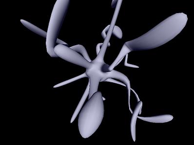
Hi, and welcome to Tutorial 2 of my XNA Shader Programming tutorial. Today we are going to work on Tutorial 1 in order to make the lighting equation a bit more interesting, by implementing Diffuse lighting.
Diffuse light
Ambient light got the following equation:
I = Aintensity * Acolor
Diffuse lighting builds on this equation, adding a directional light to the equation:
I = Aintensity x Acolor + Dintensity x Dcolor x N.L (2.1)
From this equating, you can see that we still use the Ambient light, but need two more variables for describing the color and intensity of the Diffuse light, and two vectors N and L for describing the light direction L compared to the surface normal N.
We can think of Diffuse lighting as a value that indicates how much a surface reflects light. The light that is reflected will be stronger and more visible when the angle between the Normal N and the light direction L gets smaller and smaller.
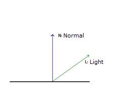
If L is parallel with N, the light will be strongest reflected, and if L is parallel with the surface, the light will be reflected with the minimal amount.
To compute the angle between L and N, we can use the Dot-product, or the scalar product. This rule is used to find the angle between two given vectors and can be defines as the following:
N.L = |N| x |L| x cos(a),
where:
|N| is the length of vector N,
|L| is the length of vector L,
cos(a) is the angle between the two vectors
Implementing the shader
We need three global variables:
float4x4    matWorldViewProj;
float4x4    matInverseWorld;
float4      vLightDirection;
We still have the worldviewprojection matrix from tutorial one, but in addition, we have the InverseWorld matrix that is used to calculate a correct normal related to the world matrix, and a light direction vLightDirection that explains what direction that light have.
We also need to define the OUT structure for our vertex shader, in order to make the correct light equation in the pixel shader:
We also need to define the OUT structure for our vertex shader, in order to make the correct light equation in the pixel shader:
struct OUT
{
    float4 Pos: POSITION;
    float3 L:    TEXCOORD0;
    float3 N:    TEXCOORD1;
};
Here we have the position Pos, the light direction L and the Normal N stored in different registers. TEXCOORDn can be used for any values, and as we don't yet use any texture coordinates, we can easily just use these registers as a storage for our two vectors.
Ok, its time for our vertex shader :
Ok, its time for our vertex shader :
OUT VertexShaderGo( float4 Pos: POSITION, float3 N: NORMAL )
{
    OUT Out = (OUT) 0;
    Out.Pos = mul(Pos, matWorldViewProj);
    Out.L = normalize(vLightDirection);
    Out.N = normalize(mul(matInverseWorld, N));
    return Out;
}
We take the position from the model file, as well as the normal, and pass it into the shader. Based on these and our global variables, we can transform the position Pos, normalize the light direction and transforming+normalizing the normal of the surface.
Then, in the pixel shader we take the values in TEXCOORD0 and put it in L, and the values in TEXCOORD1 and put it in N. These registers are filled by the vertex shader. Then we implement equation 2.1 in the pixel shader:
Then, in the pixel shader we take the values in TEXCOORD0 and put it in L, and the values in TEXCOORD1 and put it in N. These registers are filled by the vertex shader. Then we implement equation 2.1 in the pixel shader:
float4 PixelShaderGo(float3 L: TEXCOORD0, float3 N: TEXCOORD1) : COLOR
{
    float Ai = 0.8f;
    float4 Ac = float4(0.075, 0.075, 0.2, 1.0);
    float Di = 1.0f;
    float4 Dc = float4(1.0, 1.0, 1.0, 1.0);
    return Ai * Ac + Di * Dc * saturate(dot(L, N));
}
The technique for this shader is the following:
technique DiffuseLight
{
    pass P0
    {
        VertexShader = compile vs_2_0 VertexShaderGo();
        PixelShader = compile ps_2_0 PixelShaderGo();
    }
}
Ok, thats if for Diffuse light! Download the source and play around with it in order to understand it fully :) I hope that you start to see the power of shaders now and how to use them in your own application!
Download Sample
Download Sample
